Guangdong Zhicheng Champion Group Co.,Ltd.


Product Search
Contact
Tel: +86 769 87927258
Fax: +86 769 87927259
Email: sales@zhicheng-champion.com
Add: Tianxin Industrial Zone, Tangxia town, Dongguan City, Guangdong, P.R.China.
10-160KW Emergency Power System
Category:
Detail
Introduction to Working Principles
1.1 Overview
These EPS series are the power equipment that can provide a voltage- and frequency-stable power system free from power network interruption. When power failure happens, EPS can supply electric power to the load for a period. These EPS series adopt the high frequency double transformation structure with an output separation transformer and apply all the advanced digital control technologies to achieve a stable, clean, and uninterrupted output and complete network management functions.
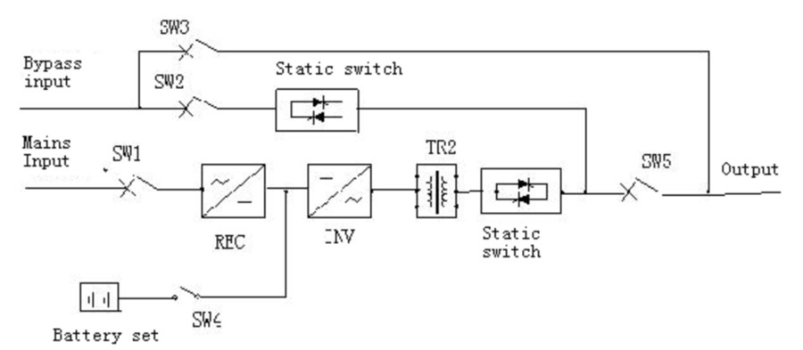
Fig.1-1
1.2 Working Principle
As shown in Fig. 1-1, EPS mainly composes a REC (rectification) module and INV (inverse transformation) module, bypass static input switch SW2, maintenance bypass air switch SW3, output separation transformer, inverse static switch, storage battery set, and input switch SW1, output air switch SW5 and so on. The circuit illustration of a single set EPS is shown in Fig. 1-2.
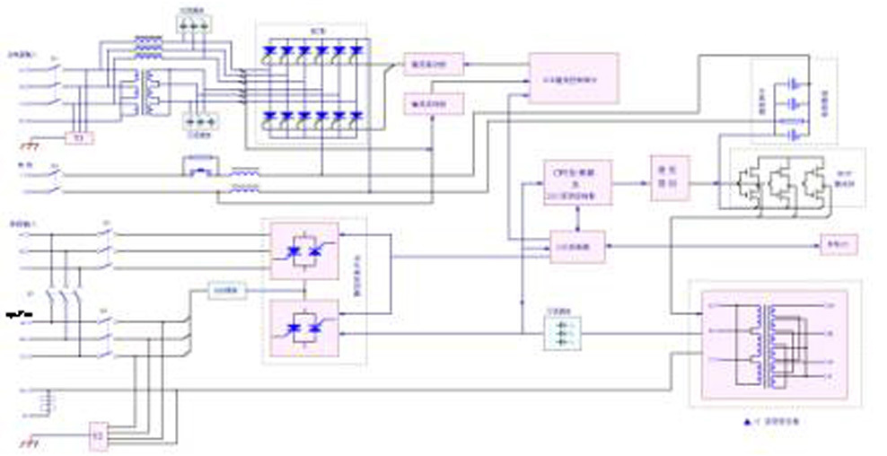
Fig. 1-2 Illustration of the Primary Circuit Working Principle
for a Single Set EPS
The main input power supply is entered through K1 air-breaker into REC rectification unit by input inductor and separation transformer. The rectifier will transform three-phase alternative current into a stable direct current power, where the rectifier also serves as an electric charger. This part of circuits adopts delay “soft start” and all-phase control technologies to increase the impulse resistant capacity of the system and stability of direct master line voltage, decrease ripples of the storage batteries and extend their life.
When storage batteries are connected via K2 and contactor, the storage battery set can be connected to DC master line and the storage batteries can supply DC power to inverter through direct current filter circuits only if direct current master line voltage reaches a certain threshold value.
Inverter adopts DSP, MCU and DDC real-time processing all-digital vector control technology and, and by digital sine wave pulse, modulates six IGBT power switch parts of DSPWM to transform the DC power supply into three-phase AC power. The output separates load terminal and input side through △/Y0 transformer, static switch, air-breaker K4 and other functional parts.
Bypass input power is input through air-breaker K3 and output after being controlled by bypass static switch.
EPS paralleling system applies digital signal processing (DSP) control technology and independent on-line logic paralleling technology. Each set of UPS introduces paralleling logic signals and circulating current test signals. Up to 8 sets of UPS can directly be paralleled in paralleling system connection. The EPS power system can realize many working modes, such as N+X redundant paralleled connection, capacity-increased parallel and serial hot backup, and so on. Without any auxiliary equipment added on, on-line EPS paralleling connection can shorten power failure time, and even eliminate power cut to achieve high reliability of the system.
1.3Working Modes
1.Normal working modes
2. Working Mode of the Batteries
3.Bypass Working Mode
4.ECO Working Mode
5.Maintenance Working Mode
6.Combined Power Supply Working Mode
7.Paralleling Working Mode
1.4Basic functions
Battery Management: The EPS system has an advanced battery management function, including battery malfunction test, prediction of backup time after battery discharge, battery self-test, etc.
Delay Soft Start: The delay soft start of the EPS system can greatly reduce the impulse to the equipment and power network during the start process of the EPS system.
Warning and Protection: The EPS system can give many forms of warnings, and the warning happening can currently be prompted immediately, accurately and specifically through sound, light, LCD, input and output node and network transmission.
Cold Start: The EPS system can directly be started with battery set when no AC input is made.
Automatic Restart after Electric Supply Recovered: The function of Automatic Restart after Electric Supply Recovered is specially designed for the application in the circumstance that the EPS equipment is connected to backup batteries. After the under-voltage protection is applied on the backup batteries, it allows EPS power source to be automatically started when AC power is re-supplied normally. The power supply mode is selected according to the working mode already set up.
Monitor System: The monitor system of this EPS system provides superior monitoring of the system itself, and supports flexible network monitor, so it can fully meet the demands of various users.
Parallel Connection: The EPS system can redundantly work in a parallel connection of up to 8 sets of EPS to meet the demands in reliability for the loads.
1.5Specifications of Performances
Parameters of the EPS System
1.Input of rectifier: See Table 1
Table 1
| Model | 10 KW | 15 KW | 20 KW | 30 KW | 40 KW | 50 KW | 60 KW | 80 KW | 100 KW | 120 KW | 140 KW | 160 KW |
| Nominal (KVA) | 10 | 15 | 20 | 30 | 40 | 50 | 60 | 80 | 100 | 120 | 140 | 160 |
| Working mode and principle |
Working mode and principle: On line power supply, static bypass switch (non-interruption switch), double transformation technology, complete separation of output power. |
|||||||||||
| Phase number | Three phases + N + G | |||||||||||
| Nominal voltage | 380VAC±25% | |||||||||||
| Nominal freq. | 50Hz±10%,60Hz±10% | |||||||||||
| Voltage harmonic distortion | <10% | |||||||||||
| Soft start | 0~100% 5sec | |||||||||||
2.Output of rectifier: See Table 2
| Model | 10 KW | 15 KW | 20 KW | 30 KW | 40 KW | 50 KW | 60 KW | 80 KW | 100 KW | 120 KW | 140 KW | 160 KW |
| Max. Output voltage | 432VDC | 448V | ||||||||||
| Charging current can be set | 10A~20A (adjustable) | |||||||||||
3.Batteries: See Table 3
Table 3
| Model
|
10 KW | 15 KW | 20 KW | 30 KW | 40 KW | 50 KW | 60 KW | 80 KW | 100 KW | 120 KW | 140 KW | 160 KW |
| 28 | 42 | 56 | 85 | 113 | 141 | 169 | 205 | 255 | 304 | 360 | 450 | |
| Number of batteries | 32节 | 33节 | ||||||||||
| Nominal battery voltage | 384VDC | 396VDC | ||||||||||
| Floating charge voltage | 432VDC | 488VDC | ||||||||||
| Charging current | 10A~20A (adjustable) | |||||||||||
4.Inverter: See Table 4
Table 4
| Model | 10 KW | 15 KW | 20 KW | 30 KW | 40 KW | 50 KW | 60 KW | 80 KW | 100 KW | 120 KW | 140 KW | 160 KW |
| Phase number | Three phases + N + G | |||||||||||
| Nominal voltage | 380VAC±1%(stead state load) | |||||||||||
| Nominal freq. | 50Hz±0.05%,60Hz±0.05%(battery power supply) | |||||||||||
| Freq. Stability: as insynchronic | <±0.05% | |||||||||||
| Freq. Stability: as synchronic | <±2% | |||||||||||
| Wave peak factor | 3:1 | |||||||||||
| Output wave form | Sine wave | |||||||||||
| Total harmonic distortion | Linear load<3%; Non-linear load<5% | |||||||||||
| Instant change of dynamic load (from 0 to 100%) |
<±5% | |||||||||||
| Instant recovery time | <10ms | |||||||||||
| Balanced load voltage | <±1%; <±5% (unbalanced load voltage) | |||||||||||
| Overload capacity | 125% 10min,150% 1Min | |||||||||||
| Inverter efficiency, of load 100% | 91 | 91 | 92 | 92 | 93 | 93 | 93 | 95 | ||||
5.Bypass: See Table 5
| Model | 10 KW | 15 KW | 20 KW | 30 KW | 40 KW | 50 KW | 60 KW | 80 KW | 100 KW | 120 KW | 140 KW | 160 KW |
| Bypass input current(A) | 19 | 28 | 38 | 56 | 78 | 95 | 114 | 152 | 189 | 227 | 265 | 303 |
| Phase number | Three phase + N + G | |||||||||||
| Nominal voltage | 380VAC±25% | |||||||||||
| Nominal frequency | 50Hz±5%,60Hz±5% | |||||||||||
| Inverter/Bypass (transforming time) | <100ms | |||||||||||
6.System: See Table6
Table 6
| Model | 10 KW | 15 KW | 20 KW | 30 KW | 40 KW | 50 KW | 60 KW | 80 KW | 100 KW | 120 KW | 140 KW | 160 KW | |||||
| Output single bypass | 19 | 28 | 38 | 56 | 78 | 95 | 114 | 152 | 189 | 227 | 265 | 303 | |||||
| Efficiency load 100% | >90% | ||||||||||||||||
| Communication port | RS232 | ||||||||||||||||
| Running temperature | 0~40℃ | ||||||||||||||||
| Relavtive humidity (不凝结) | 5%~95% | ||||||||||||||||
| Operation altitude (max.) | <1000 m (1% power lost as increased every 100m, maximum 4000m) | ||||||||||||||||
| Cool mode | Forced ventilation | ||||||||||||||||
| Noise dB (subject to load and temperature, 1 meter to the UPS) | 48-60 | 53-65 | |||||||||||||||
| Box color | Grey | ||||||||||||||||
| Input cables | Bottom / back | ||||||||||||||||
| Maintenance | Front/ Up / Left and Right side | ||||||||||||||||
| External size (WXHXD)(mm3) | 560×1140×800 | 560×1400×800 |
950×1800×850 |
1200×1800×900 | |||||||||||||
| Weight (kg) | 210 | 258 | 350 | 400 | 480 | 580 | 650 | 900 | 1200 | 1300 | 1350 | 1480 | |||||
| Input component | Line connecting terminal row | ||||||||||||||||
| Output component | Line connecting terminal row | ||||||||||||||||
* Remark: the above data are for reference. Once any changes are found, please refer to the physical sizes of the equipment.
Chapter 2: Rack Installation
2.1 Environmental requirements:
● Working temperature: 0-40˚C
● Storage temperature: -40-70˚C (with batteries installed)
-20-55˚C (without batteries installed)
● Relative humidity: 5%-95%, non-condensing
● Altitude above sea level: 1500 m, in compliance with the altitude-fall requirements set in Standard GB3859.2-93.
● Verticality: Free from vibration and vertical gradient within 5 degrees
The EPS system should be installed at the cool and clean environment with good ventilation and proper humidity. Working temperature is recommended at 20-25˚C, and humidity is controlled around 50%.
Tel: +86 769 87927258
Fax: +86 769 87927259
Email: sales@zhicheng-champion.com
Add: Tianxin Industrial Zone, Tangxia town, Dongguan City, Guangdong, P.R.China.
Subscribe
Subscribe to our newsletter
Copyright © 2022 Guangdong Zhicheng Champion Group Co., Ltd.